Mastering UG NX Corner Toolpaths: A Practical Guide
Listen up, everyone! Today, Engineer Wang is going to talk about the often-overlooked “corner” settings in UG NX. Don’t underestimate this area; many newcomers find that tools can gouge, pause, or even scrap workpieces when they reach these corners. Textbook theories are often convoluted, so today, I’ll use plain language to explain how to effectively use and adjust these settings on an actual machine to achieve beautiful, time-saving, and labor-efficient results!
I. Corner Path Extension Modes: Aggressive or Smooth?
This section primarily discusses how the tool handles sharp corners. UG NX provides several options, each with its own characteristics.
1.1 Extend and Trim
This is one of the most commonly used modes. Simply put, when the tool reaches a sharp corner, it will first along the current trajectory, “extend” slightly, then “trim” the excess part, forming a clean and sharp corner. It’s like driving through a curve, where you briefly swing out slightly before quickly cutting in. This method ensures thorough material removal at corners, especially inner corners, when machining contours. Remember, it’s not for creating rounded transitions, but for accurately reproducing the sharp corner defined in the drawing.
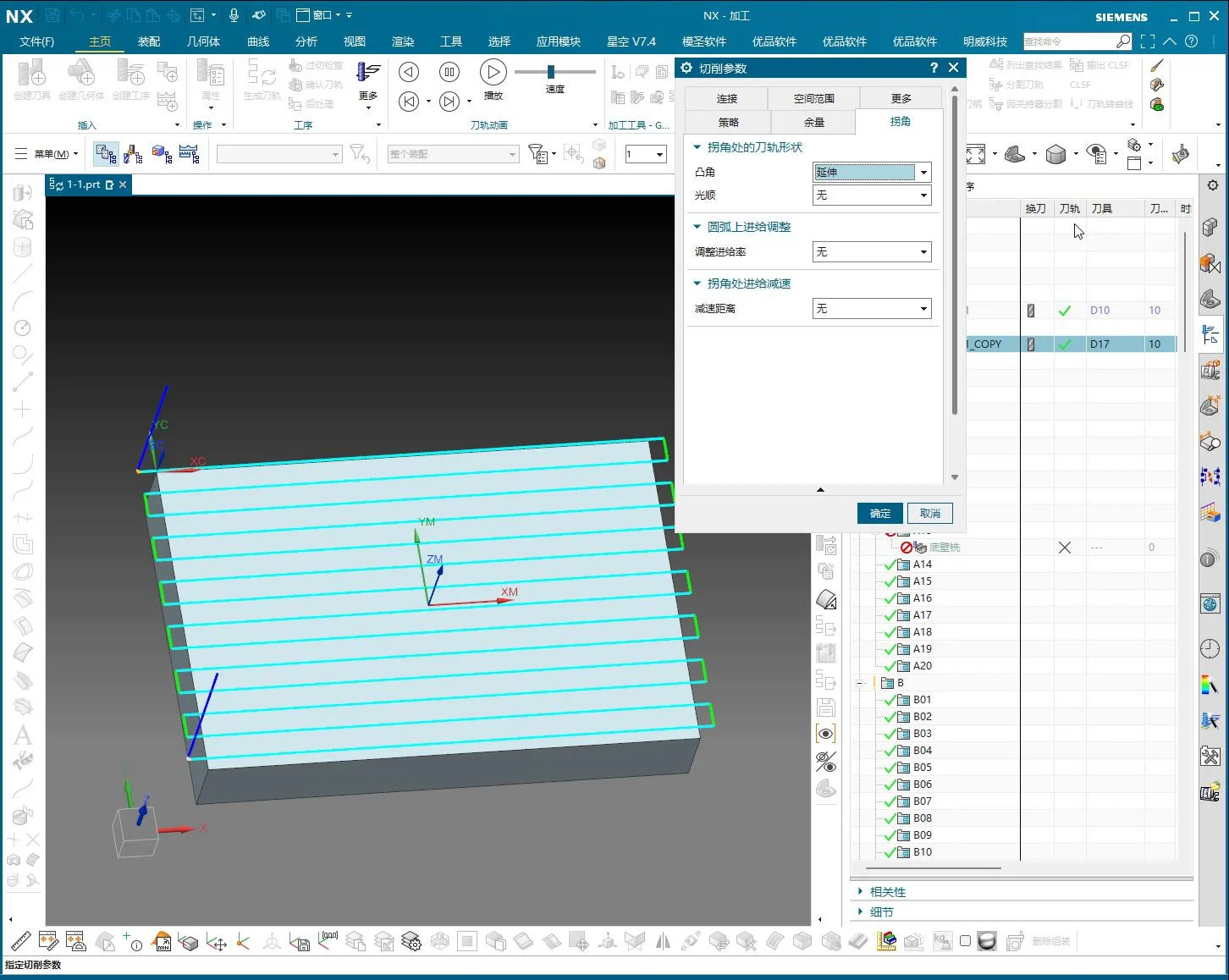
1.2 Just Extend
This option is more “straightforward.” When the tool reaches a sharp corner, it will only extend along the path, without any trimming or arc transitions. It might sound less useful, but it’s sometimes required for special processes, such as needing the tool to dwell longer at a certain point or for leaving machining allowance for subsequent finishing. However, it’s rarely used in most cases, as it can easily lead to overcutting or material residue at sharp corners.
II. Toolpath Arc Transition and Smoothing: Bid Farewell to “Square Heads”
This section is crucial for preventing machine “pauses” or “vibrations” when machining right angles. Especially during high-speed cutting, a sudden change in tool direction creates significant impact.
2.1 Object Rolling
This name sounds a bit mystical, but it simply means allowing the tool to smoothly “roll” through the corner with a preset fillet radius. It automatically transforms original sharp or right-angle corners into arcs. This results in smoother machine motion without jerks, which benefits both the machine spindle and the tool, and produces a better-looking surface finish.
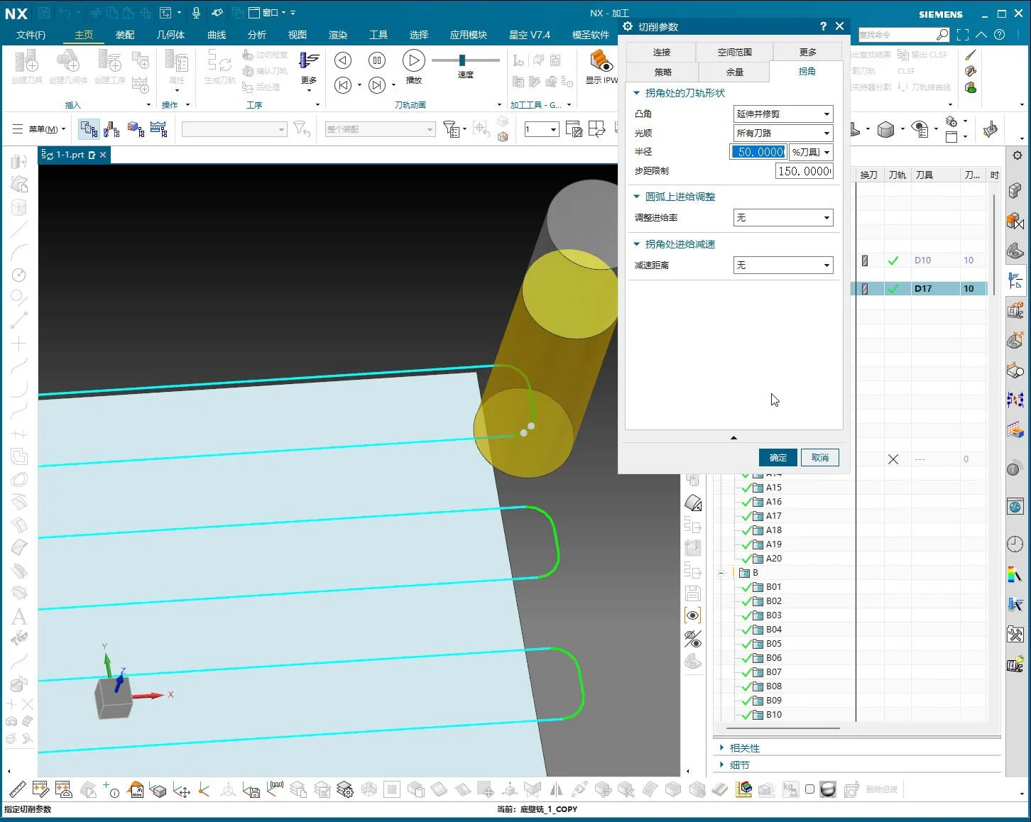
2.2 Smooth
“Smoothing” is similar to “Object Rolling” in that both aim to create a more fluid toolpath at corners. It inserts small arcs for transition along the toolpath, especially where sharp corners would otherwise exist. It’s like an experienced craftsman sharpening a knife, slightly rounding off the sharp edges to make them less “harsh,” which results in smoother cutting.
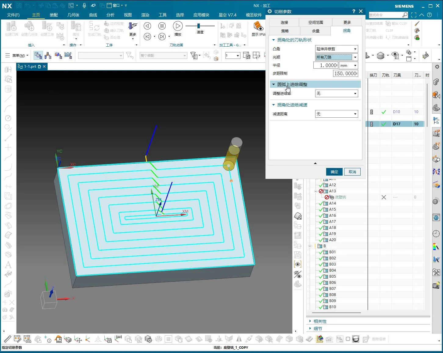
The key parameter here is Radius. You can choose to control the size of this arc by percentage (relative to tool diameter) or millimeter value. For example, if you use a D10 tool and set it to 50%, it will create an R5 fillet transition. This value is not fixed; Engineer Wang’s experience suggests:
- For inner corners or finish machining, if high precision is required, a small fillet of 0.2mm to 0.5mm, or even smaller, can be applied.
- For outer corners or rough machining, you can be bolder and apply a fillet of 1mm or even 10mm, as long as it doesn’t affect subsequent operations. This mainly depends on the material you are machining and the depth of cut.
Practical Tip: Applying arc transitions at corners effectively avoids vibration and impact generated during sudden stops and turns, extends tool life, and results in a more beautiful surface finish without “pause marks.”

III. Corner Feed Rate and Deceleration: Controlling the Cutting Rhythm
When machining corners, the tool’s feed rate is also critical. Too fast, and the tool can gouge; too slow, and it wastes time.
3.1 Feed Rate Adjustment on Arc
This setting allows you to adjust the feed rate when the tool transitions along an arc. Sometimes, to ensure the accuracy and smoothness of the arc, we slightly reduce the feed rate on the arc to prevent tool chatter.
3.2 Corner Deceleration
As the name suggests, this feature automatically reduces the feed rate when the tool approaches a corner, then resumes normal speed after passing it. This function is particularly effective when machining hard materials or when high surface quality is required. You can set the deceleration percentage, for instance, reducing it to 50% of the current feed rate. Although Engineer Wang doesn’t use it frequently, it can be a lifesaver in special situations. For example, when machining a deep cavity where chips can accumulate at corners, deceleration ensures more stable cutting.
IV. Corner Remnant Material Removal Strategy (Layout Limit/Constraint)
This “Layout Limit/Constraint” might sound a bit odd, but it addresses a very practical problem: “remnant material” at corners. When the tool machines contours, especially complex inner corners, it can sometimes leave behind small, irregular residual material. If these remnants are not cleaned, they will affect the workpiece’s accuracy and assembly.
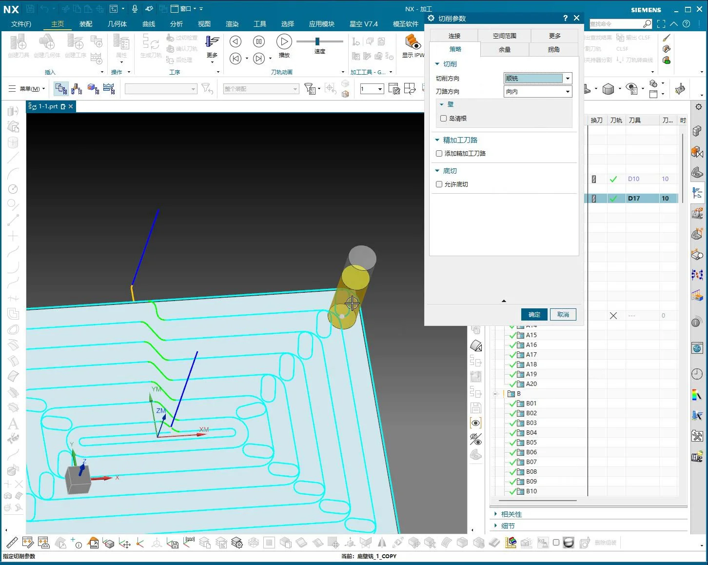
This function enables the tool to make an additional pass or sweep back and forth in a smoother manner at corners, especially in areas prone to material residue, to thoroughly clean up those “edge remnants.” You can control the range and method of remnant removal by adjusting its values. For example, if this value is set too small, some tiny remnants might be overlooked. Therefore, adjust it according to the actual situation to ensure all necessary areas are cleaned.
This is essentially a form of toolpath optimization, ensuring consistent machining quality across the entire workpiece and preventing minor issues from causing major problems.
V. Engineer Wang’s Pitfall Avoidance Guide
1. Don’t just rely on software simulation; observe the cutting sparks! No matter how good the software simulation looks, it might be different on the actual machine. Especially at corners, pay close attention to the machine’s sound, cutting sparks, and chips. If the sound is off or sparks are flying erratically, it indicates that your corner parameters might be incorrect, and the tool is overloading!
2. Prioritize arc transitions for inner corners. For most inner corners, especially smaller ones, try to use “Object Rolling” or “Smooth” functions to add arc transitions. This significantly reduces tool wear and workpiece vibration, improves machining efficiency, and avoids machine “hard stops.” For sharp outer contours, if the drawing has strict requirements, “Extend and Trim” can be used to ensure sharpness, but pay attention to cutting parameters to prevent chipping.

3. Radius settings must be flexible, not rigid. The R value is not fixed; there’s no “one-size-fits-all formula.” It depends on your tool size, material hardness, depth of cut, and final precision requirements. For roughing, it can be larger; for finishing, it needs to be smaller. You must experiment and summarize to find the most suitable parameters for your workpiece.
4. “Corner Deceleration” and “Feed Rate Adjustment on Arc” are your spare tires. You might not use them often, but they become invaluable when tackling particularly tough challenges, such as high-hardness materials, deep cavity machining, or when extreme surface quality is required. Judicious adjustment of feed rates can help you maintain machining quality without affecting the schedule.
5. Remnant material must be thoroughly cleaned. The “Layout Limit/Constraint” function is crucial in finish machining, especially in mold manufacturing. Don’t let tiny “remnants” that are hard to spot with the naked eye ruin your entire workpiece. Inspect thoroughly and think critically to ensure the tool reaches every corner and cleans everything that needs to be cleaned.